The FCU-SCB226 control board is specifically designed for the remote control of 2/4-pipe fan coils via an RS-485 interface[cite: 477]. [cite_start]It functions as a slave device using the Modbus RTU protocol to communicate with central control and monitoring stations[cite: 482].
[cite_start]This unit is ideal for home, hotel, and greenhouse automation, offering temperature measurement on two independent channels through external NTC 10k sensors[cite: 479, 483].
| Parameter [cite: 481][cite_start] | Detail [cite: 481] |
|---|---|
| Supply Voltage [cite: 480][cite_start] | 12-24V DC [cite: 480] |
| Supply Current [cite: 480] | Max. [cite_start]1.0A [cite: 480] |
| Analog Inputs [cite: 480][cite_start] | 2 (for NTC 10k Thermistors) [cite: 480] |
| Digital Inputs [cite: 480][cite_start] | 2 (Discrete) [cite: 480] |
| Valve Relay Outputs [cite: 480][cite_start] | 2 [cite: 480] |
| Fan Relay Outputs [cite: 480][cite_start] | 3 [cite: 480] |
| RS485 Slave Ports [cite: 480][cite_start] | 1 [cite: 480] |
| Operating Temperature [cite: 480][cite_start] | -20/+70°C [cite: 480] |
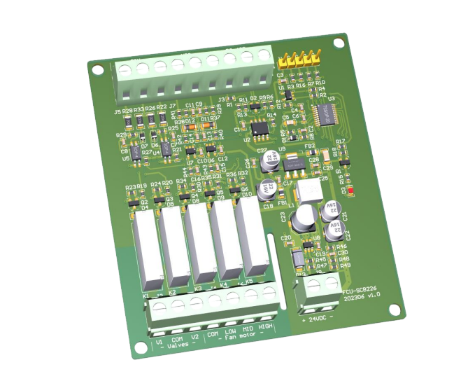
The board is powered by a 12-24V DC source using a 2-wire circuit (VDD and GND)[cite: 545]. [cite_start]Connection points are located at connector J8[cite: 540, 546].
The unit features two analog channels for temperature measurement using NTC-10K remote thermistors with 12-bit ADC accuracy[cite: 551, 553]. [cite_start]The pair of optically isolated digital inputs requires an external power source (DC 12V) and can be utilized as limit switches for motorized valves[cite: 485, 569].
There are 5 independent relays with NO contacts, each capable of switching 5.0A at 250VAC[cite: 576, 577]. [cite_start]These are organized into two functional groups[cite: 486]:
The RS485 Slave interface uses terminals A and B[cite: 567]. [cite_start]A 120 Ohm bus terminator can be added by shorting the T terminal to the B terminal if the device is at the end of the bus[cite: 567].
| Connector [cite: 539][cite_start] | Description [cite: 539] |
|---|---|
| J8 [cite: 540][cite_start] | DC Power Supply (12-24V DC) [cite: 540] |
| J7 [cite: 540][cite_start] | Dual Analog Inputs (NTC Thermistors) [cite: 540] |
| J3 [cite: 540][cite_start] | RS485 Interface [cite: 540] |
| J5 [cite: 540][cite_start] | Digital Inputs [cite: 540] |
| J2, J4 [cite: 540][cite_start] | Relay Outputs (Valves and Fan) [cite: 540] |
 [cite_start]